Brief Introduction:
Vehicle control technology is integrated into this series controller to provide efficient control of
the three-phase AC motor for the vehicle power drive system, providing the
most cost-effective design for vehicle developers and providing a flexible, comfortable and
safe handling experience for vehicle drivers and passengers.
Features:
●Applicable to Induction motor and PMSM
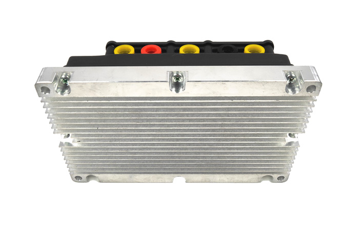
●To gain higher power density and overload capacity,SMD MOSFET and aluminum
plate cooling technology are adopted
●The power supply of control signal can be provided by12VDC or power battery
●High-performance vector control algorithm to achieve full speed range of motor
speed and precise torque control, improving vehicle power performance and comfort
●Flexible parameter adjustment function meets theexcellent
●Multi-functional I/O terminals, meeting the requirements of different applications
●Integrated high voltage pre-charge circuits, improving the all-in-one design
●Natural cooling, force air and liquid cooling are adopted, covering overall power range
●Customized software available for meeting different requirements of customers
●CAN bus communication and software update by computer programming
Typical Application:
●Applicable to all-electric or hybrid vehicles powered by rated voltage of battery 60 ~ 144 VDC
●Applicable to short-distance passenger cars, sightseeing cars, logistics vans,
sanitation vehicles andmaterial handling vehicles and other electric vehicles
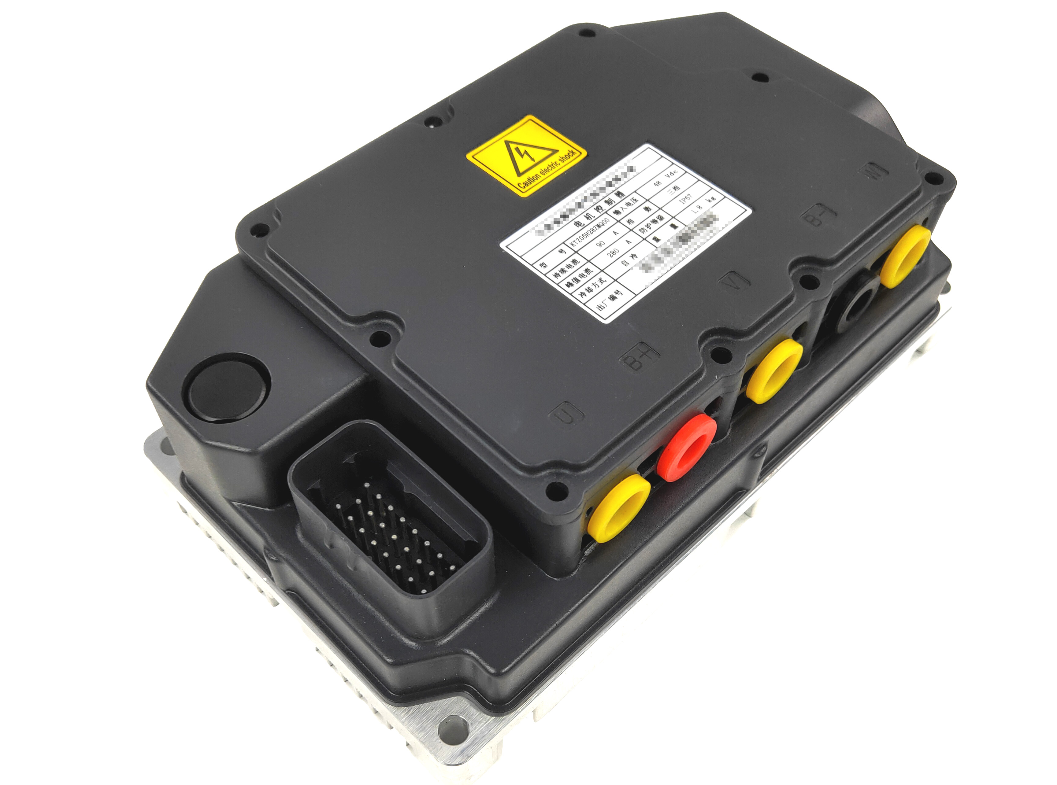
Key technical features:
Electrical characteristics
| Auxiliary power voltage |
6~16V DC |
|
| Rated battery volt |
48V DC |
Support 72V and 48V battery |
| Input volt range |
24V~72V |
|
| Rated output current |
80A |
|
| Peak output current |
280A (3s) |
|
| Rated output power |
2.5kW |
|
| Peak output power |
5kW |
|
| Highest efficiency |
≥98% |
Rated condition |
| Output freq range |
0.00~600Hz |
|
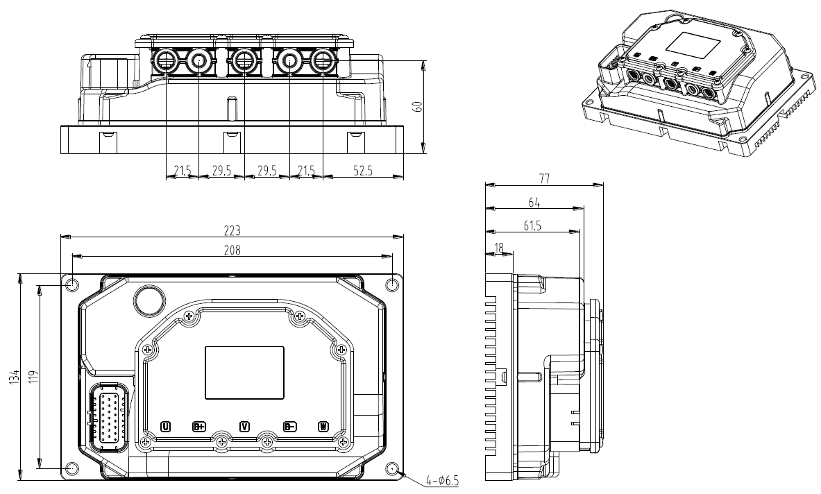
Mechanical characteristics
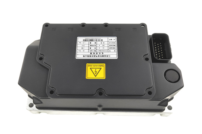
| Dimensions |
223*134*77 |
Please read external dimension below for more details |
| Installation dimensions |
L*W-Φ=208*119-4Φ6 |
Please read external dimension below for more details |
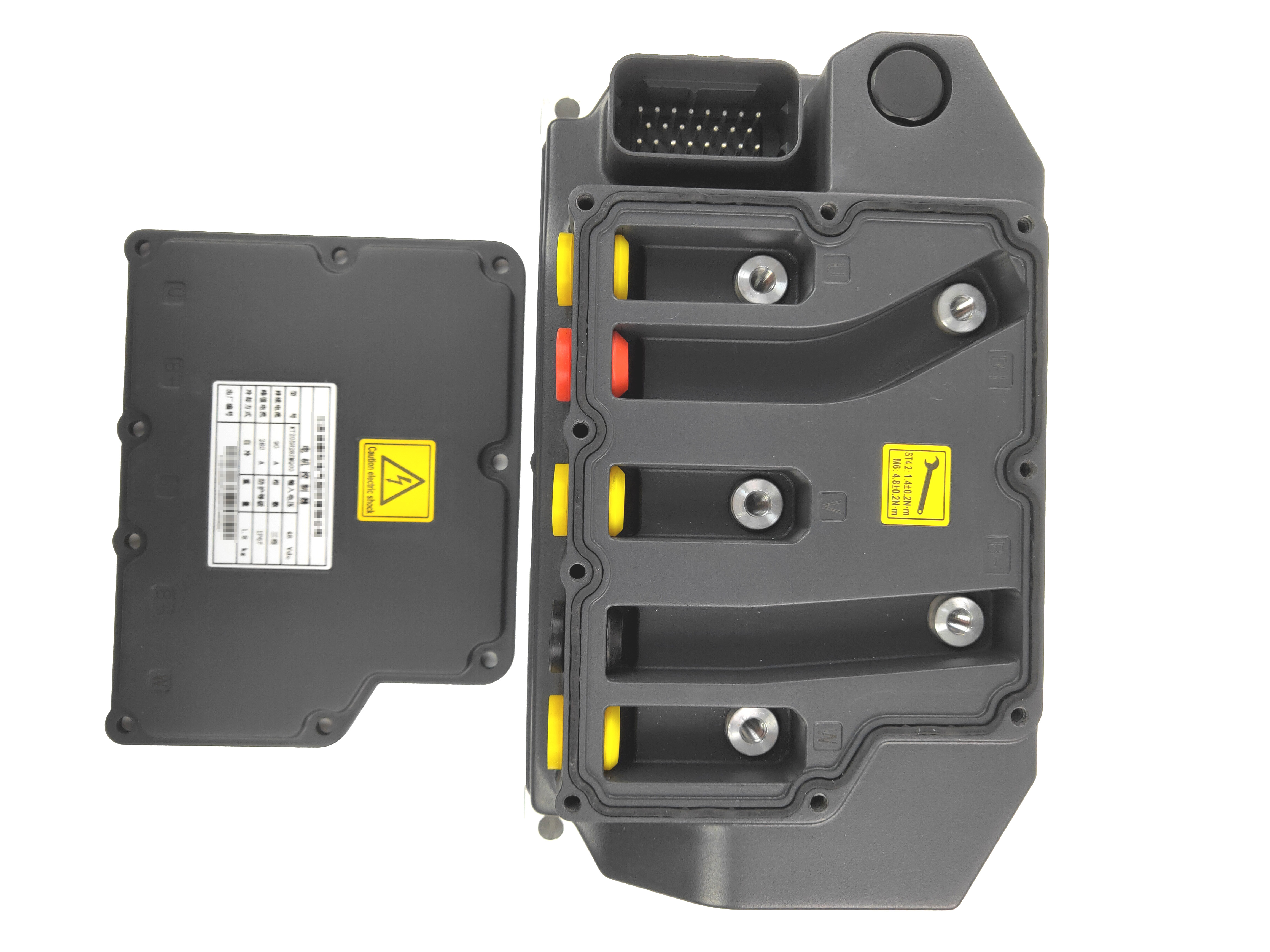
| Screw torque of protection cover |
M4*12,1.4Nm |
|
| Screw torque of power terminals |
M8*(16~20),14~16Nm |
B+、B-、U、V、W |
| Screw torque of bottom installation plate |
M6,19~21Nm |
|
| Cooling method |
Natural Cooling |
Air duct is needed
|
Control characteristics
| Control Mode |
Vector control: speed control or torque control |
| Encoder type |
Magnetic encode (TLE5012B E1000 or AS5047D) |
| Speed range |
1:1000 |
| Speed accuracy |
±0.02% |
| Start torque |
0Hz, 200% |
| Torque response |
<5ms |
| Torque accuracy |
±5% |
Basic performances
| Accel/Decel time |
0.00~60000s |
| Switching frequency |
0.7~10kHz |
| Frequency set mode |
communication or analog input control |
| Torque set mode |
communication or analog input control |
| Stop method |
Ramp to stop, coast to stop |
| Communication method |
CAN bus communication |
| Input terminals |
Digital:6 Analog:1 Power supply:1 channel |
| Output terminals |
none |
| Motor Type |
PMSP or IM |
| Motor temperature sensor |
NTC、KTY84、PT1000 |
Unique characteristics
| parameter adjustment and parameter copy/backup through control panel, PC monitoring software upgrade |
| Motor parameters auto-turning, field-weakening control, energy feedback, hill-start assist control and three groups of fault record. |
Overall protections
| Battery over-voltage |
72V |
ov1 |
| Controller over-heat |
90℃ |
oH1 |
| Motor over-heat |
130℃ |
oH2 |
The bearable lowest temperature of controller
|
-40℃ |
oH3 |
| Battery under-voltage |
|
LoU |
| Controller overload |
|
oL1 |
| Motor overload |
|
oL2 |
| Short-circuit between output and aluminum plate |
|
GdP |
| Output phase loss |
|
oPL |
| Encoder disconnected |
|
CLL |
| Auto-tuning failed |
|
tUN |
| Speed bias is large |
|
SPL |
| Current detection abnormal |
|
CtC |
| Power supply is abnormal when running |
|
|
Environment
| Storage temperature |
-40℃~+85℃,GB/T 18488.1 |
| Ambient temperature |
-40℃~+55℃,GB/T 18488.1 |
| Altitude |
0~2000m. De-rate 1% for every 100m when the altitude is above 1000 meters |
| Relative humidity |
5~95%, condensation allowed , GB/T 18488.1 |
| salt spray |
GB/T 2423.17 |
| Vibration |
Sweep vibration and random vibration, GB/T 18488.1 |
| IP grade |
IP65 |
| Insulation strength |
1500V,1min,≤10mA |
| Insulation resistance |
1000V,hot insulation resistance> 10MΩ |
| Safe grounding |
The resistance between controller conductive parts can be reached and the enclosure ground point is less than 0.1Ω |
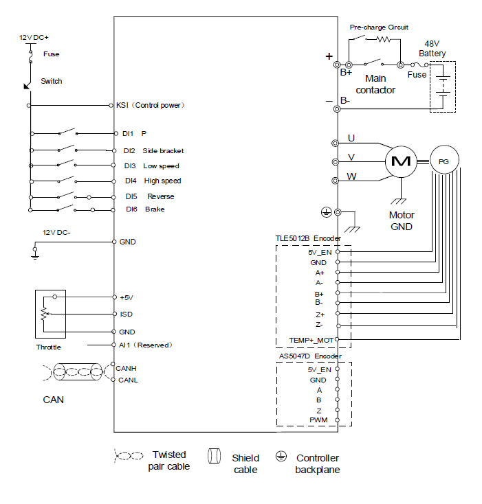
Controller Signal Connector:

The connector and terminals models related to vehicle wiring harness:AMP 770520-1/770854-1
Copper core of cable:0.5~1.25mm2, Outer diameter of insulating layer:1.7~2.7mm
| PIN |
Signal Name |
Definition |
Remark |
| 1 |
TEMP+ |
Motor temperature |
Motor temperature sensor + |
| 2 |
GND |
Magnetic encoder - |
Magnetic encoder - |
| 3 |
5V_EN |
Magnetic encoder + |
Magnetic encoder + |
| 4 |
P |
Park |
12V effective |
| 5 |
5V |
Throttle control power |
|
| 6 |
KSI |
12V battery + switch |
|
| 7 |
CANL |
CANL |
Low end of CAN
|
| 8 |
CANH |
CANH |
High end of CAN |
| 9 |
Z-(PWM) |
Encoder Z- (PWM) |
Connect to Z- when encoder is TLE5012B E1000
Connect to PWM when encoder is AS5047D
|
10
|
A- |
Encoder A- |
|
| 11 |
B- |
Encoder B- |
|
| 12 |
ISD |
Throttle control signal |
0-5VDS |
| 13 |
BC |
Side bracket signal |
When 12V side bracket signal is
enable, the system control is valid
|
14
|
LOW |
Low speed gear |
12V effective |
| 15 |
AI |
Analog signal (Reserved) |
|
| 16 |
Z+(Z) |
Encoder Z+(Z) |
Connect to Z+ when encoder is TLE5012B E1000
Connect to Z when encoder is AS5047D
|
| 17 |
A+(A) |
Encoder A+ (A) |
Connect to A+ when encoder is TLE5012B E1000
Connect to A when encoder is AS5047D
|
| 18 |
B+ (B) |
Encoder B+(B) |
Connect to B+ when encoder is TLE5012B E1000
Connect to B when encoder is AS5047D
|
| 19 |
GND |
Motor temperature sensor - |
Motor temperature sensor - |
| 20 |
HIGH |
High speed gear |
12V effective |
| 21 |
Reverse |
Reverse |
12V effective |
| 22 |
Brake |
Brake |
12V effective |
| 23 |
GND |
Isolated 12V- |
|
Note: Customer shall pay close attention to the items marked by *
Power input & output terminals:
| Terminal Name |
Signal Definition |
Copper core: mm2, Metal terminal/Max size of cable insulation: mm |
Rated voltage/current |
| + |
Battery input + |
25/35,9.5~12 |
300V DC/150Arms |
| - |
Battery input - |
25/35,9.5~12 |
300V DC/150Arms |
| U |
Output U phase |
25/35,9.5~12 |
300V DC/150Arms |
| V |
Output V phase |
25/35,9.5~12 |
300V DC/150Arms |
| W |
Output W phase |
25/35,9.5~12 |
300V DC/150Arms |
Commissioning tools
CAN communication:USB-CAN adapter
Programming computer:Computer equipped with corresponding software:


 Top
Top